
An inexpensive scope for hobbyists and learners
Team Members: Anup S, Sowmiya Balaji, Amishi Gupta
Role: First Author
Skills picked up: PCB Layout Design, Embedded Systems Design, DIY Reflow Soldering, Upverter (Layout Design Tool), SoC programming
Publications: Realtime On-chip Waveform Monitoring at IEEE ICACCI 2018.
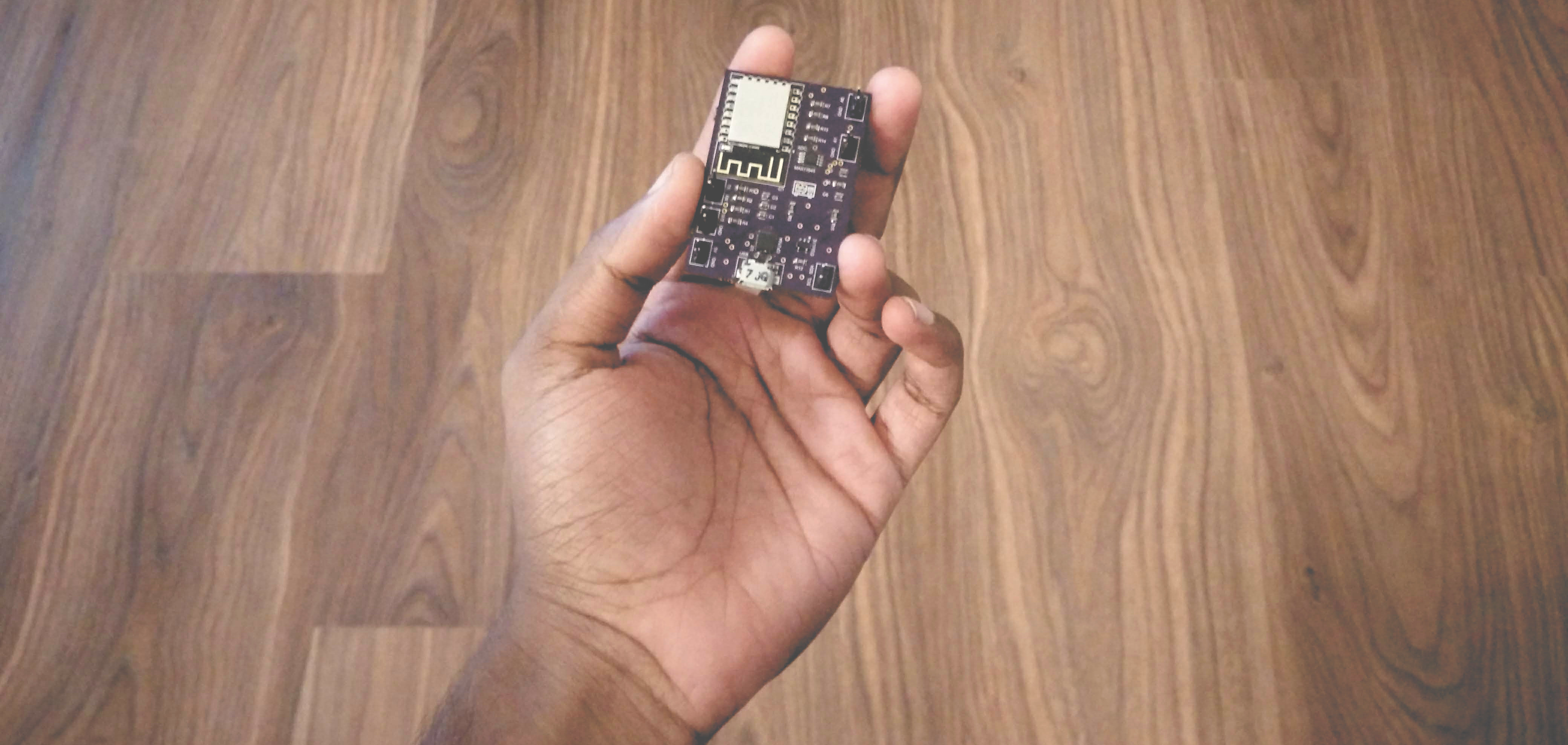
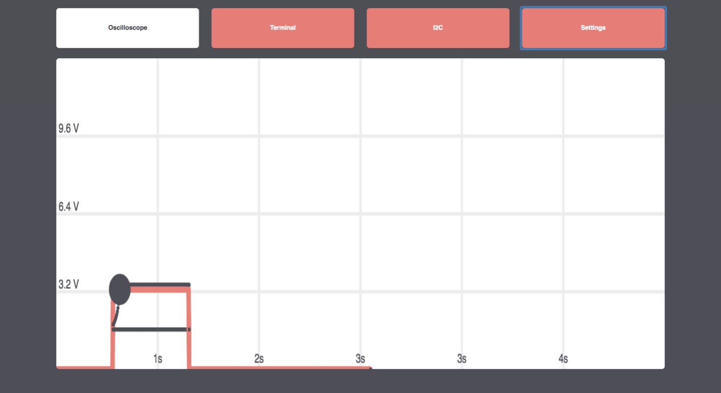
DopeScope is an attempt at delivering an inexpensive, un-intimidating scope for Universities in India with poor scientific infrastructure.
DopeScope connects to your phone/computer over WiFi and the browser acts as a display device. The signal processing computation is also done on the browser using its higher computational power rather than relying on an expensive DSP chip and it only costs $16.
An employability report conducted in India, concluded that 80% of all engineers in India are unemployable. These numbers were much lower for the Universities that were ranked outside the top 100. After asking a couple of students in Electrical and Electronics Engineering, about why they felt like they lacked practical skills, the most common answer we got was something like this,
“We don’t feel comfortable using equipment in the lab as it’s too expensive. We’re often restricted by lab assistants and professors from truly experimenting. “
Although scopes are very robust, we couldn’t go around convincing students that it’s actually hard to break one, so we decided to make a cheap one. We also added a smattering of other features to make things interesting for hobbyists.
We started by thinking about how the interaction should work. Existing multimeters or scopes use a proprietary app. We wanted it to work using just the browser on a smartphone or a laptop.
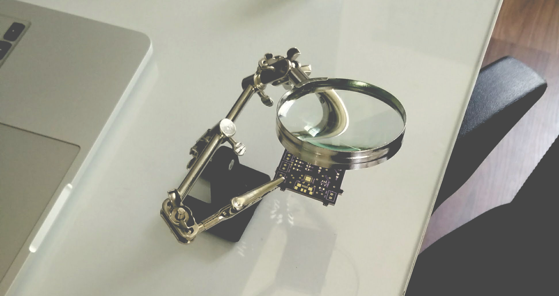
The first step was to build a prototype:
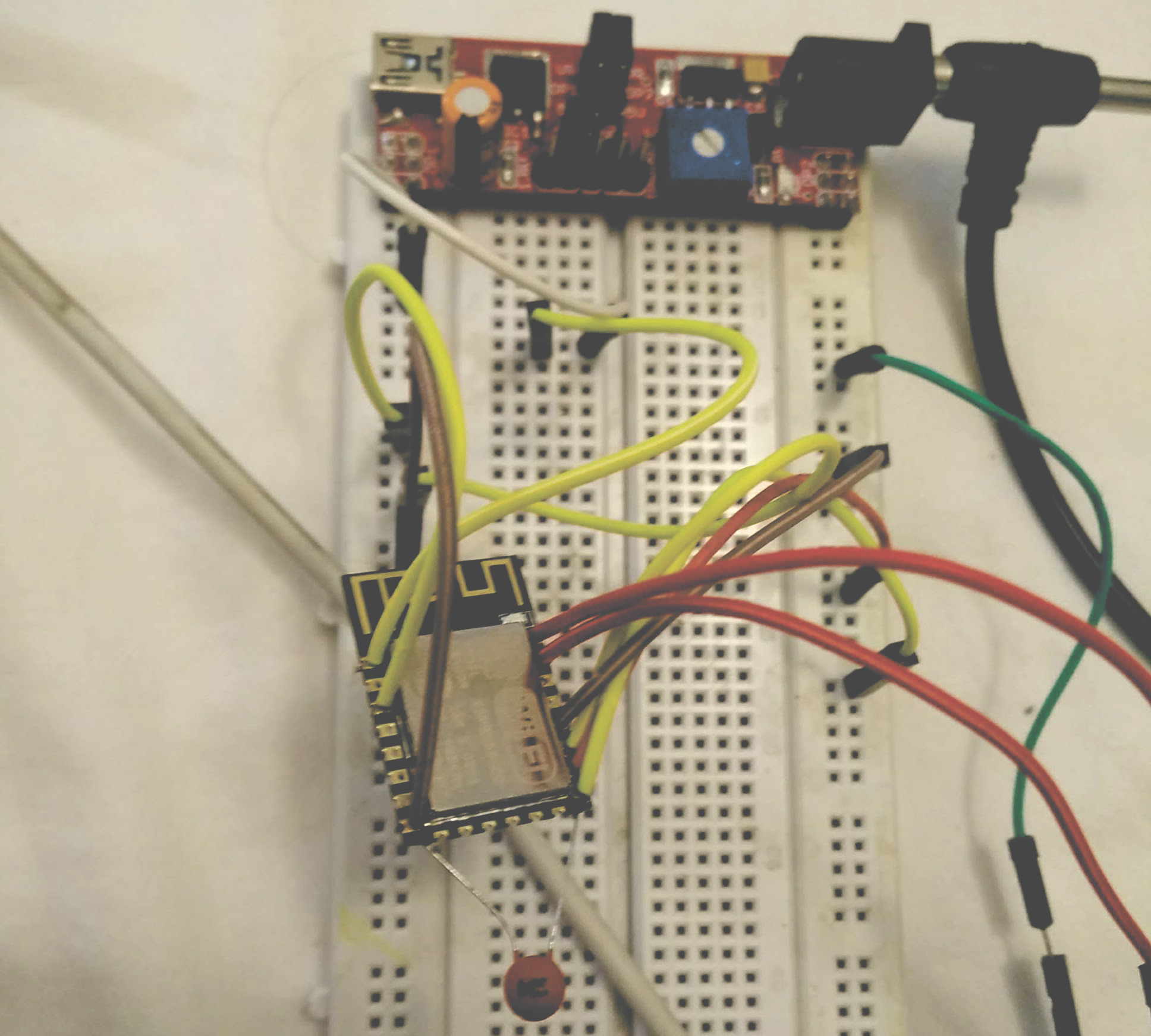
The prototype was built using an ESP8266. The on-board ADC was used to develop the software.
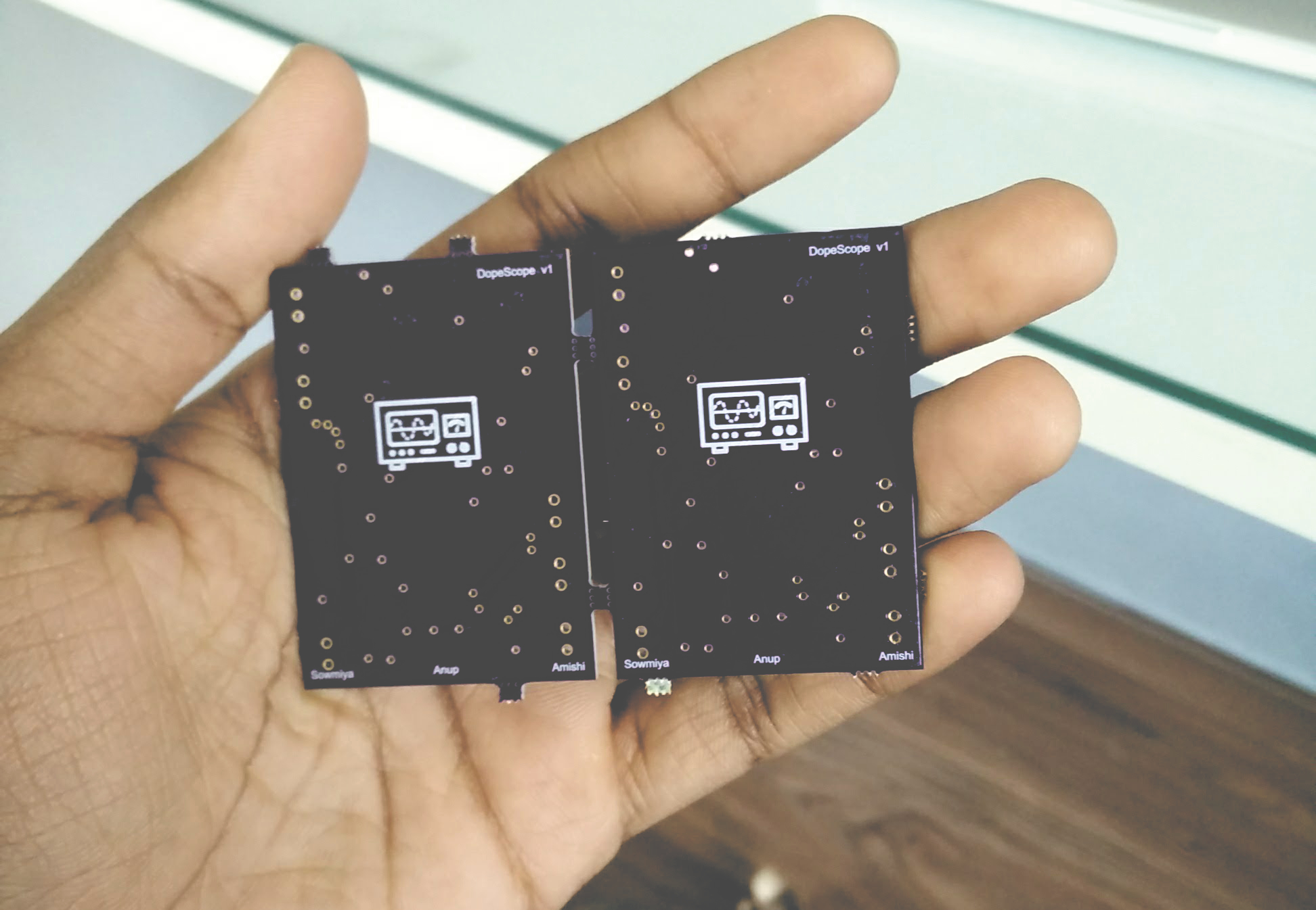
The next step was to design the PCB itself. The usual option is Eagle CAD, but I had trouble finding the parts that were needed so I used Upverter.
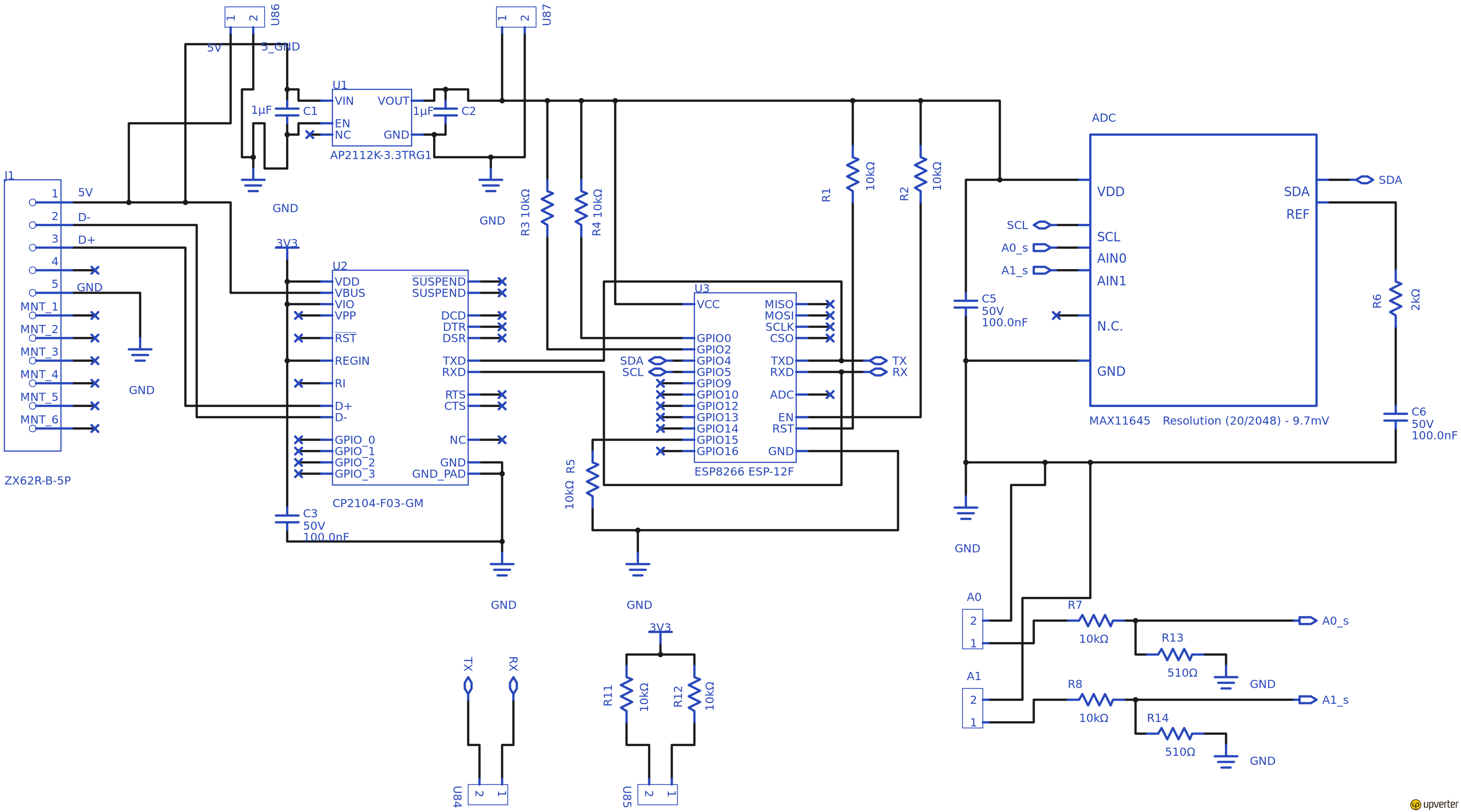
After designing the schematic, the actual layout design had to be done and the unpopulated board had to be fabricated. To fabricate the board, I relied on OSHPark.
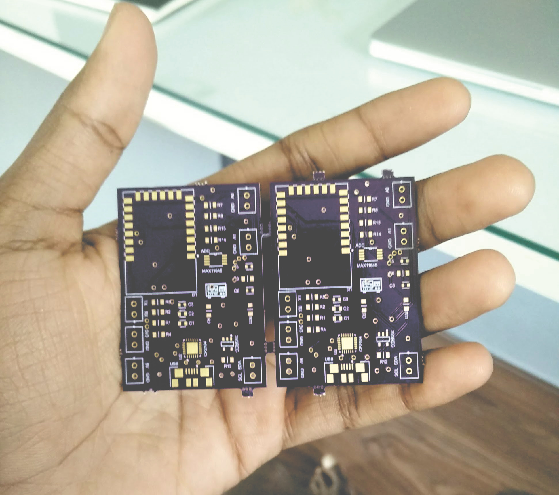
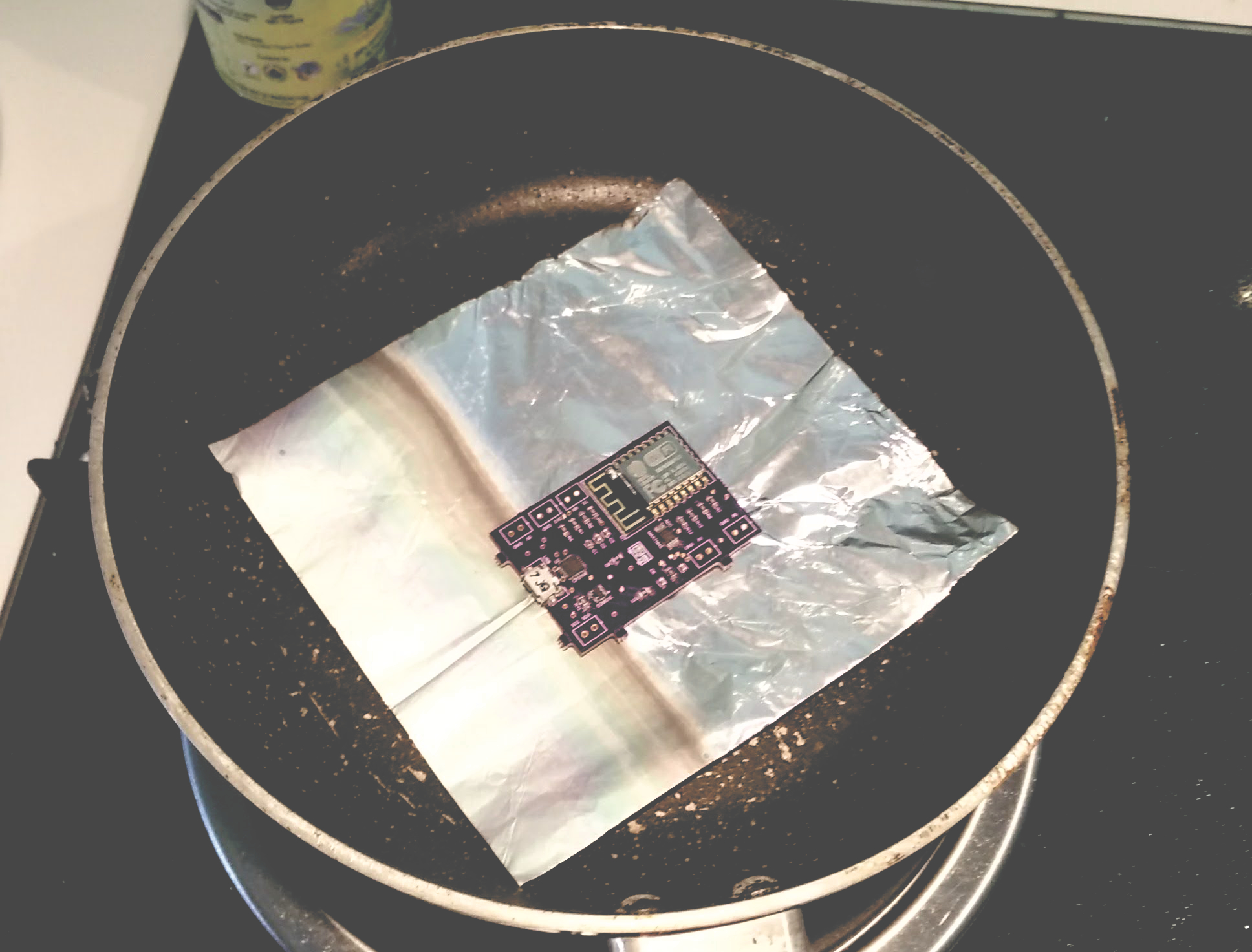
To populate the PCB, as we were using SMDs, usually a reflow oven is used. As we didn’t have access to a reflow oven, we relied on a DIY one made at home. We placed the SMD parts and used a piece of foil on a skillet to reflow the PCB.
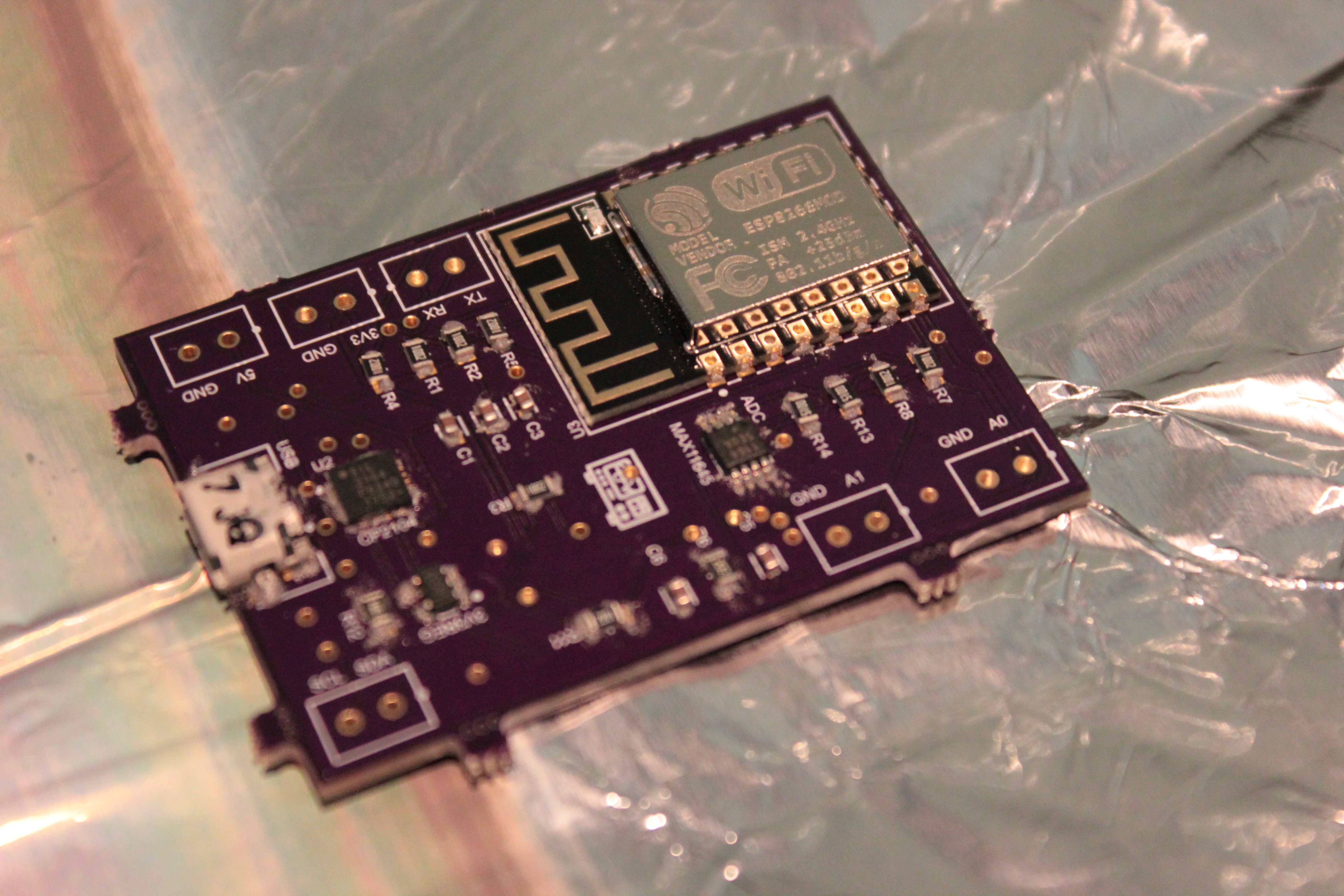
All done. To make testing easier we used the device in unipolar mode. The device can be easily converted to bipolar mode as the ADC is software configurable.
You can find complete details in our dissertation below. You can also download Gerber Files using the button below and order your own boards.
This project was part of our undergraduate dissertation.